
Table of Contents:
Executive Summary
Educational Objectives
Background Information
Procedures
Concluding Activities
An indispensable component of the control system is the actuator. The actuator is the
first system component to actually move, converting electrical energy into mechanical
motion. The most common type of actuator is the electrical motor. In this experiment, you
will build a dc motor and in the process learn the components of a dc motor. You will
also learn how a dc motor works.
Educational Objectives
After performing this experiment, a student should be able to:
1. Construct a dc motor.
2. Explain the operation of electric motors in general and DC motors in particular
Introduction
Motors are classified as either DC or AC, depending on the type of power they use. AC motors have some advantages over the DC motors: They tend to be smaller, more reliable, and less expensive. However, they generally run at a fixed speed that is determined by the line frequency. DC motors have speed-control capabilities, which means that speed, torque, and even direction of rotation can be changed at any time to meet new conditions. Also, smaller DC motors commonly operate at lower voltages, which makes them easier to interface with control electronics. A simple motor has 6 parts
Theory of Operation - The discovery that led to the invention of the electric motor was simply this: A current carrying conductor will experience a force when placed in a magnetic field. The conductor can be of any metal - iron, copper, aluminum, and so on. The direction of the force is perpendicular to both the magnetic field and the current as shown in Figure 1. The magnitude of the force on the wire can be calculated from the following equation:
F = IBL sin 
where
F = force on the conductor (in Newtons)
I = current through the conductor (in amperes)
B = magnetic flux density (in gauss)
L = length of the wire (in meters)
= angle
between the magnetic field and current
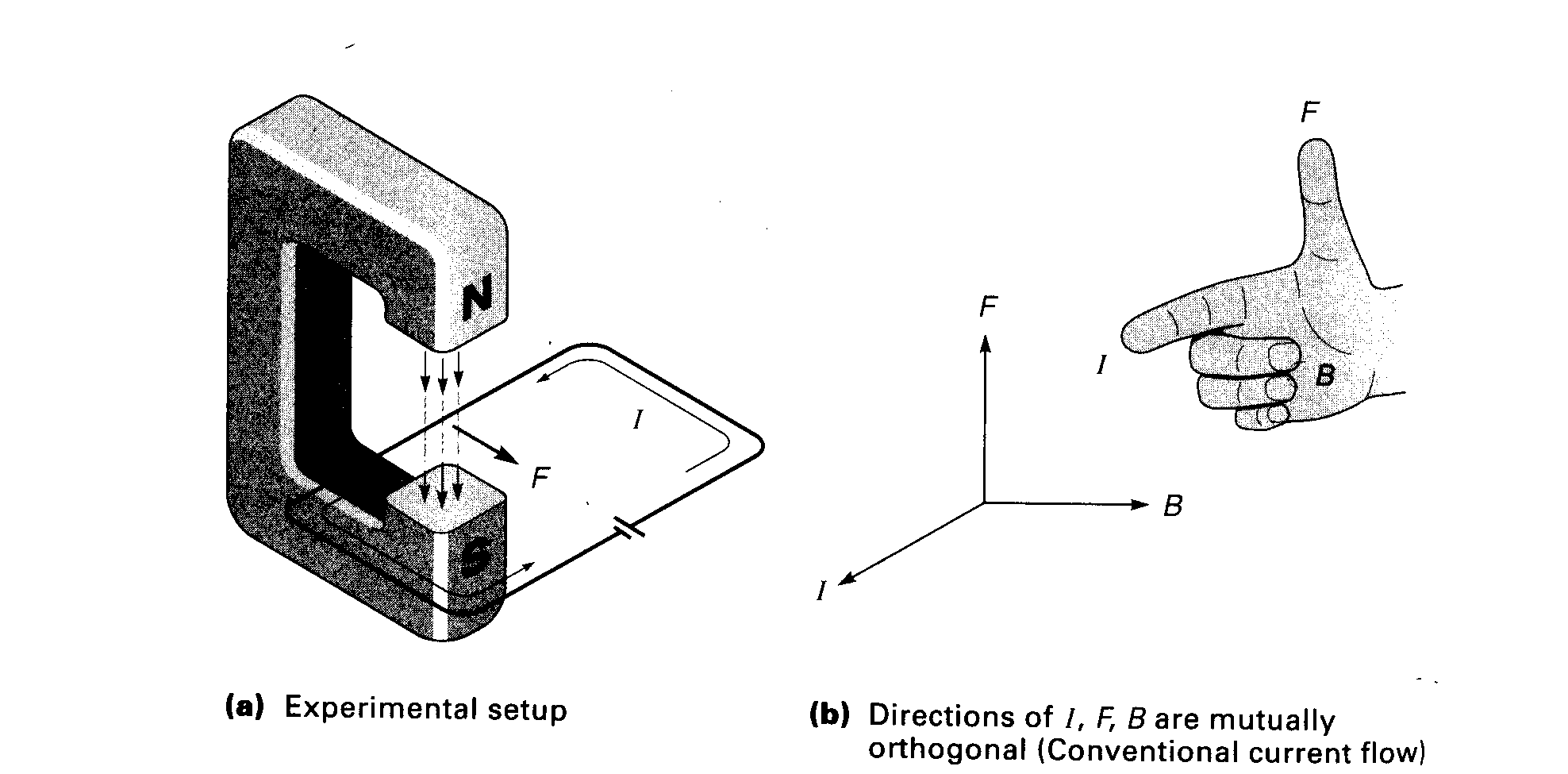
Figure 1: Action of force on a wire in a magnetic field (figure taken from Modern Control Technology by Christopher T. Kilian).
An electric motor must harness this force in such a way as to cause a rotary motion. This can be done by forming the wire in a loop and placing it in the magnetic field as shown in Figure 2. The loop (or coil) of wire is allowed to rotate about the axis shown and is called the armature winding. The armature is placed in a magnetic field called the field. The commutator and brushes supply current to the armature while allowing it to rotate.

Figure 2: A simple DC motor action (figure taken from Modern Control Technology by Christopher T. Kilian).
To understand how the motor works, look at Figure 2(a). Notice that wire segments A and B of the coil are in the same magnetic field, but the current in wire segment A is coming out of the page, whereas the current in wire segment B is going in. Applying the force diagram from Figure 1, we see that wire segment A of the coil would force up, whereas wire segment B would be forced down. These forces would cause the coil to rotate clockwise. Figure 2(b) shows the situation after the coil has rotated 90 degrees. The current has now reversed direction in the coil because the commutator contacts have rotated and are now making contact with the opposite brush. Now, wire segment A of the coil will be force down and wire segment B up, which causes the armature to continue rotating clockwise. Torque is the rotational force a motor can exert.
To reverse the direction of the motor, polarity of the voltage to the commutator is reversed. This causes the forces on the armature coil to be reversed, and the motor would then run in the opposite direction.
Figure 3 shows the armature of a practical motor. Notice that there are multiple coils and each coil experiences the forces describe earlier and so contributes to the overall torque of the motor. Each coil is connected to a separate pair of commutator segments, causing the current in each coil to switch directions at the proper time for that individual coil.

Figure 3: The armature of a practical motor. (figure taken from Modern Control Technology by Christopher T. Kilian).
Procedure to assemble dc motor from the kit
Follow the directions in the kit to assemble your motor. If you need help with the assembly, look at the assembled motor available in the lab
After performing this experiment, you should consult the website "http://www.howstuffworks.com/motor.htm". Write, in your own words, a report on "How a DC Motor works."
References:
[1] Kilian, C. T., "Modern Control Technology:
Components and Systems," West Publishing Company, 1996.